
An oil groove is a small feature with a large effect on a bronze bushing. Its pattern controls lubricant distribution, while its position changes the available load-bearing area. Choosing by appearance or a catalogue name alone can cause leakage or premature wear.
This guide compares common bronze bushing oil groove types and explains what a production drawing must contain. JEDBUSHING manufactures custom grooved bronze bushings from centrifugal cast and other suitable blanks, then machines the lubrication features to an approved drawing.
Which Oil Groove Pattern Fits a Bronze Bushing?
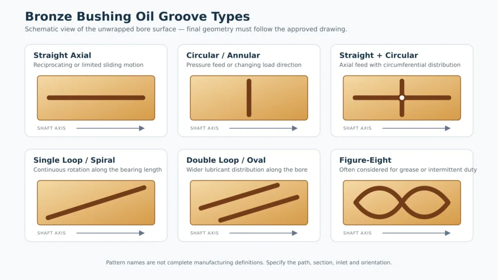
Begin with four facts: shaft motion, load direction, lubricant and supply method. A pattern that works with pressure-fed oil may not suit periodic greasing, and a groove suitable for continuous rotation may not distribute lubricant during short reciprocating travel.
| Groove pattern | Typical use | Design caution |
|---|---|---|
| Straight axial | Reciprocating or limited sliding motion | Usually kept away from the principal loaded zone and stopped before the ends |
| Circular or annular | Pressure-fed lubrication or varying load direction | Reduces effective bearing length and may increase lubricant flow |
| Straight and circular | Axial feed combined with circumferential distribution | The intersection and ring position must match the inlet and load zone |
| Single loop or spiral | Continuous rotation with lubricant distributed along the bore | Groove hand and orientation may depend on shaft rotation |
| Double loop or double oval | Wider distribution along a longer bearing | Additional groove area reduces the supporting surface |
| Figure-eight | Grease lubrication or intermittent service | Should not be copied into an oil-film application without review |
Oil flows readily, whereas grease needs a groove that can hold and distribute a more viscous lubricant. Groove cross-sections may be radiused, V-shaped or rectangular, but no profile is universally correct. Width and depth must support the required lubricant volume without removing unnecessary bearing area.
Load location is equally important. A groove across the principal loaded zone interrupts the running surface and can disturb film formation. Whenever possible, place the lubricant inlet and main distribution path in an unloaded or lower-loaded region. For reversing, oscillating or variable-direction loads, the arrangement requires a specific review rather than a default catalogue pattern.
Names also vary among suppliers. “Single loop,” “oval,” and numbered styles may describe similar-looking but different geometry. For a repeatable oil groove bushing, the drawing—not the pattern name—must control production.
What Must the Engineering Drawing Specify?
A note stating only “standard oil groove” is not enough for production. The drawing or a controlled groove detail should define:
- Finished bushing ID, OD, length and tolerances
- Groove path and orientation inside the bore
- Groove width, depth and cross-sectional profile
- Oil-hole diameter, location and connection to the groove
- Distance from each groove end to the bushing edge
- Shaft rotation or reciprocating direction
- Known loaded and unloaded zones
- Edge radius, blending and deburring requirements
- Final bore surface finish and inspection points
If a separate groove sketch is used, connect it to the correct part number and drawing revision. Do not assume that a shop will interpret a photographed sample, trade name or old supplier code in exactly the same way.
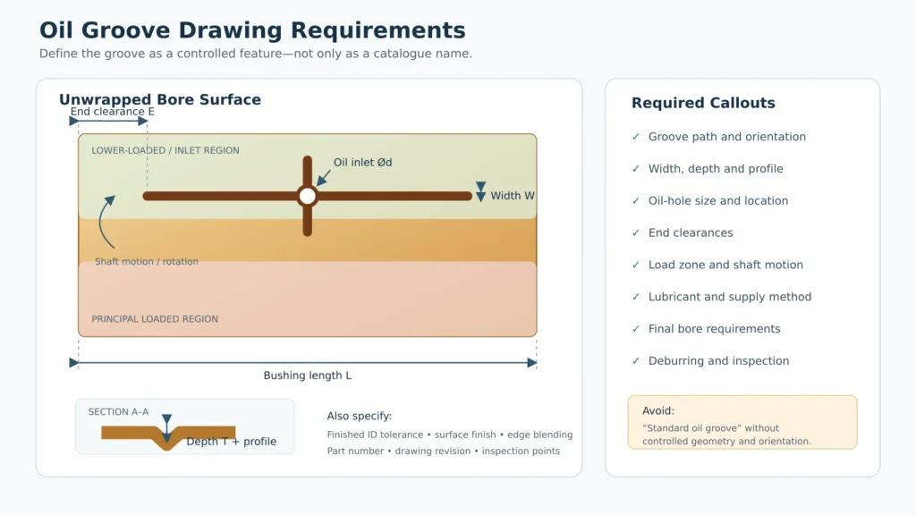
Grooves are normally machined after the cast blank has been prepared and the bore has established reference surfaces. Machining sequence matters because internal grooving, clamping and thin wall sections can affect the final bore. Inspection should therefore confirm groove position and oil-hole connection as well as the finished bore size, surface condition and absence of damaging burrs.
For replacement parts, provide the original drawing whenever possible. Measurements from a worn grooved sleeve bearing can support review, but wear may have enlarged the groove, rounded its edges or removed evidence of the original depth.
Send Your Drawing for a Grooved Bronze Bushing Quote
JEDBUSHING can review a defined groove drawing or discuss a manufacturable arrangement before quotation. Send the finished dimensions, bronze grade, quantity, shaft motion, speed, load direction, lubricant, supply method and inspection requirements.
If the groove has not been finalized, also provide the oil or grease inlet position and available information about the mating shaft. Any proposed geometry should be approved by the customer’s engineer before production. Contact JEDBUSHING to request a review of your custom bronze bushing.
Frequently Asked Questions
Can oil grooves be machined into an already finished bronze bushing?
Sometimes. The shop must check remaining wall thickness, clamping access, distortion risk, machining allowance and the required final bore tolerance before modifying the part.
Can the original groove pattern be reproduced from a worn bushing?
Not reliably from the worn part alone. Measurements, photographs and service information can support a review, but wear may have changed the original width, depth and edge form.
Can thin-wall bronze bushings have internal oil grooves?
Possibly, but there is no universal minimum wall thickness. Groove depth, bushing diameter, material, clamping method and final dimensional tolerance must be evaluated together.
Is a grooved cast bronze bushing self-lubricating?
No. A machined groove distributes lubricant supplied to the bearing; it does not create a renewable lubricant source. Oil-impregnated bronze bushings and graphite-plugged bushings use different lubrication systems.